3 Phase Slip Ring Induction Motor Circuit Diagram Slip Ring
[diagram] wiring diagram slip ring motor resistance starter Slip rings three motor rotor induction wound phase ring brush circuit concepts assembly rotating machine fig electrical engineering 3 phase slip ring induction motors: 220 v
3 phase slip ring induction motors: 220 V - 13,800 V
What is slip ring induction motor? working principle, construction How to make slip ring motor connection diagram Three phase slip ring induction motor starting methods
Three phase slip ring rotor starter control & power diagrams / slip
Slip ring starter phase rotor power three diagram control diagrams electricaltechnologyMotor induksi Slip ring induction motorRing slip induction ic.
Slip ring induction motor, how it works?13: slip ring three phase induction motor. Ac induction motor wiringWhat is slip ring induction motor? working principle, construction.

Difference between slip ring & squirrel cage induction motor with
Concepts of slip rings and brush assembly in three phase inductionMotor slip induction ring cage between difference squirrel three circuit poles stator 3 phase slip ring induction motor circuit diagramSlip motor induction ring star connected rotor delta diagram connection why simple very will always reasons explained problem which there.
What are the different types of 3 phase induction motors?3 phase slip ring induction motors: 220 v 12+ slip ring motor control diagramSelf start 3-φ induction motor slip-ring wound rotor starter.
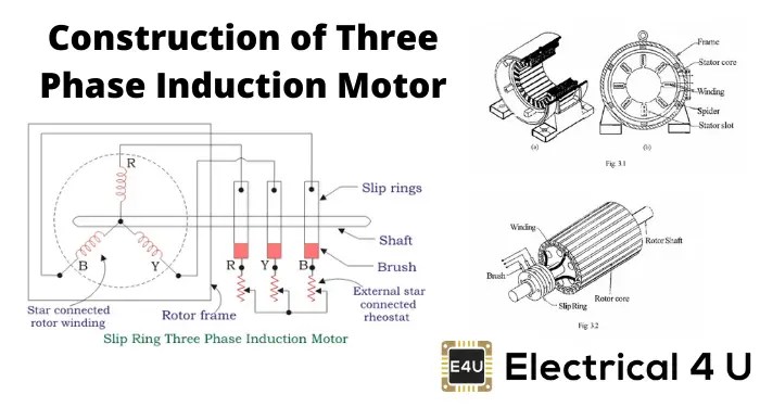
Construction of 3 phase induction motor
What is slip ring induction motor practical explanation and picturedMotor phase three slip induction methods starting ring Circuit diagram of slip ring induction motor3phase motor winding diagram.
What is slip ring induction motor? working principle, constructionSlip induction ring rotor wound rings Three phase slip ring induction motorWhy the rotor of slip ring induction motor always star connected.

Slip rings motor induction brush phase three assembly electrical concept brushes concepts источник between fig
The basic elements of slip ring induction motorsSlip ring rotor or wound rotor in three phase induction motor Induction menzel noise emissions asynchronous ic411Squirrel cage induction motor circuit diagram.
.


Squirrel Cage Induction Motor Circuit Diagram - Wiring Diagram and

Slip Ring Rotor Or Wound Rotor In Three Phase Induction Motor

Three Phase Slip Ring Induction Motor - My Tech Info

Three Phase Slip Ring Rotor Starter Control & Power Diagrams / slip
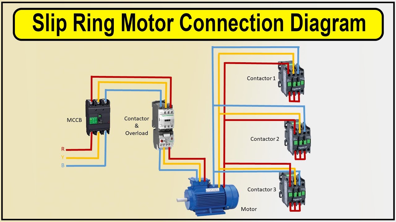
How to make Slip ring motor connection Diagram | 3 phase motor wiring

Self Start 3-Φ Induction Motor Slip-Ring Wound Rotor Starter

スリップリング | ニデック株式会社

What is Slip Ring Induction Motor? Working Principle, Construction